


- Home »
- Technical support »
- Assembly instructions
Assembly instructions
1. TEM Thickness
2. TEM Reliability
3. TEM Mechanical Properties
4. Wires
5. Metallized TEM
6. TEM Moisture Protection
7. TEM Mounting Instructions
8. Metallized TEM Mounting
9. TEM Connection to Power Supply Source
10. Power Supply Considerations
11. Supply Voltage Considerations
 The base height of each type of Kryotherm TEMs is given in the company product catalogue.
The overall TEM thickness ranges within the base height ± 0,15 mm unless otherwise specified. The standard height variation within one production lot does not exceed ± 0,05 mm. Kryotherm common parallelism of the produced TEM’s is 0,05 mm. (*)
If several TEM’s are to be installed in one thermoelectric unit, they are to be manufactured in accordance with such strict requirements to the TEM’s height tolerance and parallelism as ± 0,025 mm and 0,03 mm respectively. Another production option available with Kryotherm is ± 15 micron tolerance on TEM base height and 15 micron parallelism when so specified.
Reliability is one of the major criterion of thermoelectric module (TEC) selection. TEC’s are considered to be highly reliable components due to their solid-state construction.
However, Kryotherm experience in thermoelectrics made it possible to highlight the following main causes of premature TEC failure:
- TEC improper operation and its faulty mounting, in the first place, which leads to TEC mechanical failure;
- TEC improper installation, which provides poor thermal contact between TEC’s hot side and heat exchanger;
- Insufficient dissipation of heat generated on TEC’s hot side or increased voltage supply, which leads to TEC’s overheating during its operation;
- Fast temperature alteration of TEC’s hot and (or) cold side on wide scale (thermal cycling).
General instructions on how to properly install Kryotherm TEC’s are given below. We strongly recommend you to go over the TEC Mounting Instructions especially if it is your first experience in doing so. If you choose the best fitted TEC’s for you application or design/ calculate a thermoelectric cooling assembly , it is highly important to take into account the processing temperature on TEC’s hot side, which should not exceed the maximum processing temperature given in the TEC’s specification. Otherwise, this may result in intense degradation changes in semiconductor material parameters or cause TEC failure. Kryotherm off-the-shelf TEC’s maximum processing temperature of 80°C, 120°C, 150°C, and 200°C. TECs with processing temperature of 120°C, 150°C and 200°C have additional index HT(120), HT(150) and HT(200), respectively.
For applications requiring strict temperature cycling the KRYOTHERM produces special coolers – with C index in their name – with design allowing our customers to minimize the destructive effect of periodic mechanical stresses occurring at temperature cycling. Such modules, under other equal conditions, sustain the number of temperature cycles by several degrees larger in comparison with usual TECs.
For applications requiring strict temperature cycling KRYOTHERM produces special modules coolers – indicated by a “C” index in their name – with mechanical design that allows our customers to minimize the destructive effects of periodic mechanical stresses that occur with temperature cycling. Such modules, under other equal conditions, sustain the number of temperature cycles by AN ORDER OF MAGNITUDE several degrees larger in comparison with standard TECs.
According to specifications used by KRYOTHERM Company during production of its products, one stage thermoelectric coolers do not change their properties under the following conditions:
- sinusoidal vibration with frequency ranging from 10 Hz to 50 Hz, with vibration displacement amplitude 0.5mm;
- under the influence of mechanical shocks of a single action with a peak shock acceleration of 20g with a shock pulse duration of 2÷20 ms;
- when exposed to multiple mechanical shocks with a peak shock acceleration of 7g with a shock pulse duration of 2÷20 ms;

Kryotherm tends to supply TEC’s with attached lead wires to facilitate TEC’s installation and power supply connection. Wire gauge and length are to be specified by our customers. The minimum wire length is 20 mm. The standard tolerance on stripping and pre-tinning of loose ends of lead wires is ± 1,0 mm. Kryotherm standard tolerance on wire length is ± 2% at wire length exceeding 50 mm, and ± 1 mm for shorter wires. Kryotherm TEC’s with protruding outer tabs (electrodes) are equipped with colour shrink tubes to electrically isolate the soldering joint of wire attachment to TEC’s outer tabs. Much attention and care should be paid if lead wire attachment is done outside Kryotherm factory. It is highly important to use Bi-Sn solder with 1390C melting temperature for for standard and HT(120) coolers and POS-61 solder - for high-temperature HT (150) coolers and tin-antimony solder for high-temperature HT (200) coolers.
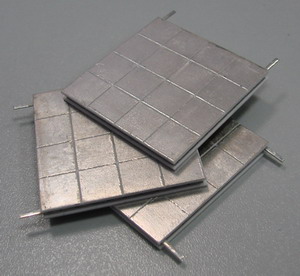
Kryotherm metallized TECs make up one of the supply options. Metallized TECs are not subject to lapping. They are solder-mounted onto heat sinks or heat exchangers. TEC’s metallized external surfaces of the substrate material plates can be coated with 950C solder to ease TEC’s soldering procedure.
On special request the solder with melting temperature of 117°C can be used for standard coolers, and for HT (150) coolers – with 139°C. Coolers with processing temperature up to 200°C can be also tinned with solder having a melting temperature of 183°C.
Kryotherm gold-coated metallized TEC’s are specifically produced for such applications as telecommunication industry when TEC’s are to be non-flux soldered.

To protect TEC’s from moisture and condensation, we suggest heading for the sealing option when Kryotherm TECs are sealed along the perimeter with silicone or epoxy sealant – they are shown by S, E indices in the name of thermoelectric cooler. The sealing techniques employed and up-to-date sealing materials make it possible to exclude the reverse heat transfer (i.e. the heat transfer from TEC’s hot side to its cold side) that appears when the sealant is being applied. The reduction in TEC’s DTmax should not be more than 1 – 1,5°C. It is highly recommended not to seal TEC’s yourself since this can lead to unintentional TEC damage. KRYOTHERM recommends strongly to its customers not to seal their coolers by their own efforts. Otherwise, KRYOTHERM do not bear any responsibility whatsoever as to the TEC’s performance and their possible damage.
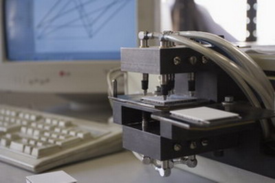
Please follow the given mounting instructions to attach Kryotherm polished TECs to a thermoelectric cooling assembly, which consists of hot heat sink, TEC, and cooled plate (the same mounting steps are applicable for other cases as well).
- Prepare the surfaces of heatsink and plate. For this it is required to grind the surfaces of heatsink and plate providing for flatness of at least 0.035 mm (25 micron) on the linear dimension of TEC being installed. In order to prevent bending and distortion of heatsink and plate during assembly, the holes for tightening screws shall be arranged as close to the thermoelectric cooler as possible. Moreover, it is advisable that the bolt holes are arranged on the line of stiffening ribs of heatsink.
- Apply thin and uniform layer of heat conducting paste (for example, KPT-8) on thermoelectric cooler and heatsink.
- Mount thermoelectric cooler by its hot side to heatsink. Hot side of the cooler can be easily determined according to the rule outlined under the title “Connecting to Power Supply Unit”. Thoroughly with uniform effort grind in the cooler to heatsink surface till obvious resistance to cooler movements appears. Remove excessive paste appearing on the cooler edges.
- Perform operation outlined in p.p. 2-3 for cooler cold side and plate being cooled. In this case it is required to move the plate slightly along the cooler cold side.
- Tighten the hot heatsink and the plate to be cooled to each other using heat insulating bushes. The material recommended for production of heat insulating bushes is polycaproamide (caprolon). Tighten the assembly cooler with extreme care turning the tightening screws one after another in several steps. In case the assembly cooler consisting of several coolers is being installed, heatsink and plate should be tightened beginning from the screw being the nearest to the centre of assembly cooler. During the assembly gradually tighten each screw checking if possible the contact of the cooler with the plane of heatsink and plate.
Note: KRYOTHERM Company recommends the following values of mounting force (Pm) during assembly of non-metallized TECs:
|
Cooler type |
Pm |
|
Microcoolers |
2- 6 kg/cm2 |
|
Standard single-stage coolers |
5- 12 kg/cm2 |
|
High-efficient single-stage coolers |
8-12 kg/cm2 |
|
Multistage coolers |
3- 10 kg/cm2 |
Please use the following formula to determine the required screw torque:
T= ((Pm *S) / N) * K * d
Where:
T - screw torque
Pm - mounting pressure
S - total surface area of TEMs in assembly
N - number of screws
K - given coefficient of friction (for example, K=0,2 for steel; K=0,15 for nylon)
d - screw nominal diameter.

- Prepare the surface of heatsink – by grinding or polishing obtain the flatness at least of 25 micron on the linear dimension of TEC being mounted. Prior the installation clean thoroughly the surfaces of thermoelectric cooler and heatsink.
- The heatsink surface shall be suitable for soldering, i.e. the heatsink shall be manufactured of or coated by adequate material, for example, by copper or nickel. After cleaning the heatsink surface should be tinned with assembly solder (type of solder is given if TEC specifications) and moistened with flux.
- Degrease the surface of the cooler being installed and apply thin layer of flux on it. Heat the preliminarily tinned and cleaned heatsink surface up to the temperature exceeding by 20°C the temperature of assembly solder (given in TEC specifications). Put the cooler onto the heatsink surface and wait for several seconds in order that the solder on the cooler melts, and the excessive flux evaporates. When all the solder is melted the cooler will tend to float on the solder. Slight blow-off and hold down of the cooler will improve its installation.
- Cool the assembly unit and cure the solder. In case more than one cooler is used in the assembly unit, these coolers shall be held down with an object having the surface of the required size with the required tolerance on flatness during the soldering.
9. TEC Connection to Power Supply Source
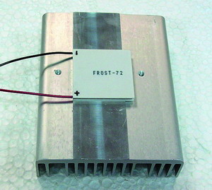
To determine the negative and positive terminals of a Kryotherm TEC, it is recommended to place the TEC face down so that its side equipped with protruding electrodes or lead wires is the TEC bottom. The protruding electrode/ lead wire on your right is positive, whereas the electrode/ lead wire on your left is negative. When TEC is supplied with DC current, its bottom side becomes hot and its upper side gets cold.
With sealed TECs, it might be difficult to determine which TEC side is equipped with lead wires because the TEC is sealed along its perimeter. In this case the colour of the lead wire is a guide, which makes it possible to distinguish between the TEC positive terminal, which has red gauge attached, and its negative terminal with black gauge attached, if not specified otherwise.
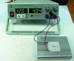
The positive and negative module leads should be connected to the respective positive and negative terminals of a DC power source.
Single stage TECs are current - reversible. In other words, reversing the TEC polarity will swap the TEC cold side into the hot one and vice versa. When TEC polarity is used, additional heat penetration along the lead wires to the TEC side equipped with the lead wires should be taken into consideration.
10. Power Supply Considerations
Thermoelectric coolers (TECs) should be powered from the direct current source. We recommend for efficient cooler operation the level of current flutter does not exceed 5% (maximum allowed level is 10%).
If it is necessary for multistage coolers to obtain the substantial temperature drop, the level of flutter shall not exceed 2%. It is recommended also to reduce in maximum extent possible the level of flutter in the power supply circuit of TECs used as coolers for precision receivers and parametric devices.
Using the regulated DC power supply coolers it is possible to obtain the accuracy of temperature maintenance on the object being cooled equal to 1°C. If more accurate temperature stabilization is required, temperature control unit is included into power supply circuit of TEC providing for feedback of the object being cooled with the power supply unit. Such circuits permits to maintain the temperature of the object with accuracy from 0.5 to 10-5°C depending on the type of the control unit used and of the power supply unit.
11. Supply Voltage Considerations
TEC operating mode - the required maximum cooling capacity and efficiency- predetermine the voltage rating to be supplied per one module. It is highly important to remember that the supplied voltage per TEC should not exceed the maximum voltage (Umax) specified for this particular type of TEC.
For example, in the case of high performance TECs such as FROST, SNOWBALL, and ICE series with the Umax being equal to appr. 16 Volts, we recommend to feed the TECs with 12 Volts, which is around 75% of their specified Umax. We consider this way of choosing TEC voltage to be optimal to provide large cooling capacity (Qc) at high-rated efficiency of a TE module. Coefficient of performance (COP) is a measure of the efficiency of a TEC and is defined as TEC cooling capacity (Qc) divided by the electric input power (P). When Kryotherm high performance TECs are supplied with over 12 Volts, the increase in TEC cooling capacity is negligible and COP of a TEC drops.
To provide high COP of a thermoelectric system that operates on a relatively low dT (dT << dTmax), it is recommended to mount several TECs into the system to supply each of the TECs with a lower voltage of around 6 to 9 Volts. If the need arises to increase specific cooling capacity of FROST, SNOWBALL, or ICE TECs, the TECs should be supplied with over 12 Volts with the generated heat being effectively dissipated from the TEC hot side.
The same principle of voltage optimization to supply TECs with 75% of their Umax is applied to all the modules, although their Umax may be different from the one mentioned above. At the same time, heat dissipation from the hot side and power supply characteristics should necessarily be taken into consideration in each particular case.
With high performance powerful TECs of DRIFT series, the optimal supplied voltage ranges 12 - 18 Volts to achieve great cooling capacity at the highest possible COP value, which is vital for such applications as CPU cooling.
When calculating electrical parameters of a TEC working point, it should be noted that once the TEC is in its running mode, the input current goes down 20 - 35 %. According to the Seebeck effect, the increase in temperature differential between the TEC hot and cold sides results in greater thermal emf. This leads to smaller voltage drop and, consequently, reduction in current running across the TEC.
![]()
![]()
![]()
KRYOTHERM
6 Aerodromnaya street
Saint-Petersburg,
197348 Russia
Tel: +7 (812) 394-1310
Fax: +7 (812) 394-1267
Email: info@kryotherm.ru